625
Item nr.
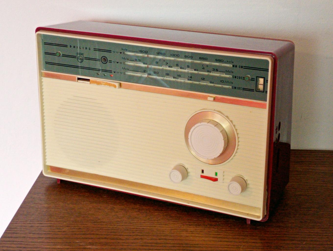
| Production | The Netherlands, 1963. |
|---|---|
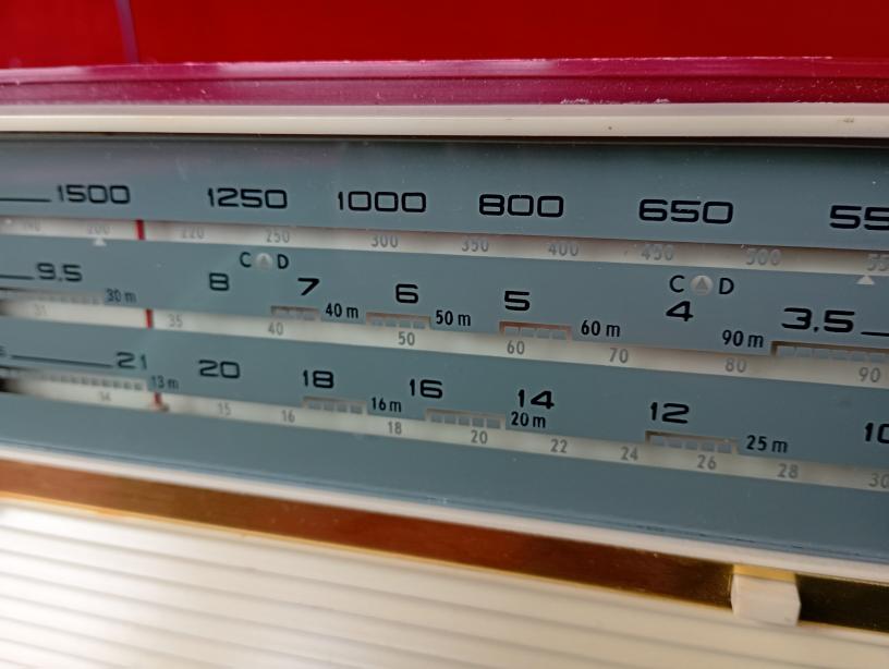
| Bands | MW (525-1605kc), TB (3.2-9.8Mc), SW (9.8-21.75Mc); IF is 452kc. |
| Semi- conductors | OC170 (mixer), 2xAF117 (IF), 2xOC71 (AF), 2xOC72 (output), OC75 (pickup preamp), OA79 (det), OA79(limiter), GL8 (aerial safety), 7121D (light). |
| Cabinet | Plastic. Size 34x23x13cm. |
| Power | Batt 6V (4 or 8 D-cells), 40mA. |
| Documents | Schema. |
 Dutch Philips sets do not often have Conelrad marks. Also, the neon bulb to protect the circuitry from static on the antenna is quite unusual for Philips sets. These probably have to do with the intended export countries and use.
 This radio tunes the Medium Wave, used almost all over the world. The first Shortwave band covers the 90m, 75m, 60m, 49m, 41m, and 31m broadcast band; the radio has no 120m band.
The set plays on 6V battery, and you can use it with four D-cells, but you can also place eight in two parallel chains. The lower load of the batteries will give you more than twice the playing time (and fewer trips to the battery shop).
The 7121D pilot light is not a dial illumination, but a battery check. In the schema, see that resistor R38 keeps C47 charged to battery voltage, and pushing the check button SK4 discharges it through lamp L, allowing the experienced user to estimate the battery condition. The schema of the B4X45T shows a different arrangement, where the lamp charges rather than discharges the C, and this arrangement is built in my B4X35T.
The radio has one extra transistor T8 of type OC75, that is not used for radio reception, but solely as a preamp for the pickup entry.
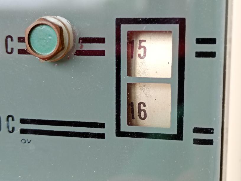
The top right corner has a numerical indication of the dial.
| Obtained | 3/2026 from NVHR Swap meet; sn=A034503. |
|---|---|
| Condition | 8; band switch broken. |
| Value (est.) | 15€. |
| Sound sample | PLAY SOUND The Tropical Band (roughly 1.6 to 5.8MHz) offers a lot to listen, but much of it is in Single Side Band. Using the Erres RP763.1 as a Radio Frequent BFO (the "Two Receiver" method) I overhear a Belgian Ham in the 80m band clearly. |
| Needs | Band switch knob. |
 even including the brass decorative strips, but the band switch misses some decorative parts. A photo (from BogotaAuctions) shows what it looks like.
 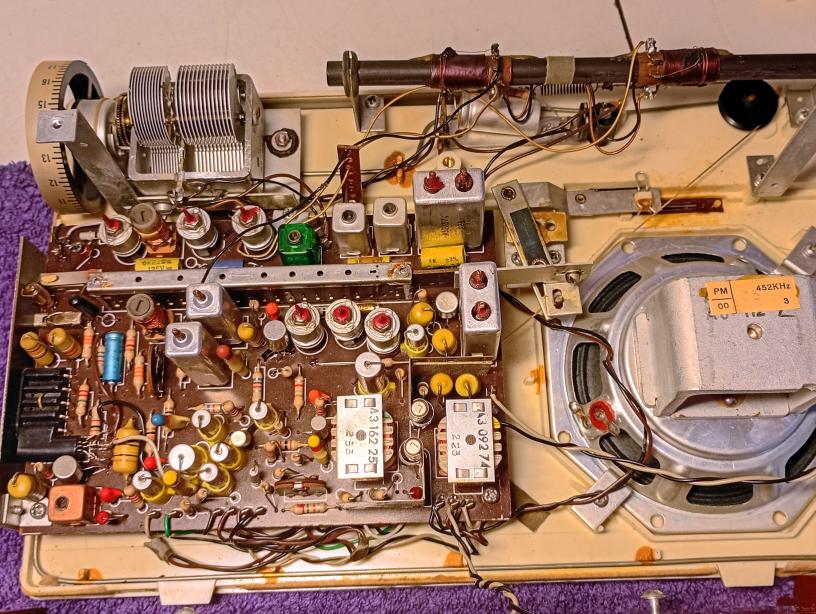 On the inside picture you can easily recognise some of the parts. In top, under the ferrite rod, the battery check light with its capacitor. Top left, the tuning cap with connected number wheel. The band switch runs horizontally over the PCB and a metal lever connects it to the knob on the front. In the left edge, between the earth and aerial jacks, is the neon bulb for antenna protection. On the left the pickup entry with source switch. The black transistor left of the band switch is the OC75 for pickup amplification. Power switch, volume and tone control are mounted on the front panel and connected to the PCB with the many wires in the bottom.
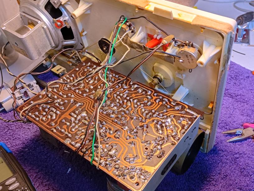 The mixer transistor was dead, which occurs often with early Philips germanium transistors, because the develop dendrites. Fred helped me to an AF139, and it was possible to get under the PCB and change the transistor.